How to Design a Playground
Learn how to design a playground with some simple easy steps and starting creating your playground equipment today!
In this section we cover many steps on how to create playgrounds such as...
-
Choosing a suitable site for your equipment.
-
Preparing a preliminary site plan.
-
Preparing a scaled plan
Follow the step by step guides provided. You will require some basic mathematic skills and some simple tools to complete these tasks. This process can be fun and will aid in your awareness of the considerations of purchasing and installing new playground equipment.
You will be required to gather information regarding your site, make an educated decision on the best location for your new equipment, take measurements of the site including any obstacles and create an analysis of your site which will be submitted through to our office where our professional team of designers and architects will prepare an interesting and imaginative design and quotation.
Choosing a suitable site.
There is no point installing playground equipment in a site that is just not practical so some investigation will need to be taken before choosing the site as a suitable location for the proposed works. Things to consider are as follows:
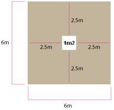
Physical size of the area. Consider the type of equipment the customer is looking to install. Australian school recommendations ask for 2.5m around the extremities of the equipment, so this would mean we need to allow 5m of clear ground space in both directions before considering the space taken by the actual equipment. For example if the area is 6m x 6m then we must take away our 2.5m from the front, back, left and right of any equipment this would leave us with only 1m x 1m of ground space left for our equipment. Obviously this would not be an appropriate space for a playground.
Fall of the ground level. Whilst playground equipment can be installed on sloped ground it would be considered anything greater than 1m in 20m should be avoided. If the fall is greater than this it would be worth considering another site. If this is the only site available with no other possible locations and other factors look suitable then I would suggest getting advice from the office regarding a design to suit the fall. Should this be the case we would need accurate measurements of the direction and amount of fall and any changes or undulations in the area.
Services such as power, water, gas and other cabling are always likely to be within the area. Take extra time to look for tell tale signs of services such as pits, pipes or conduit on buildings, drinking fountains, taps, fire hydrants, gas or water meters and always ask your customer if they are aware of any services in the area? If there are service pits do we need to maintain access to these?
Tip1:
Often recently laid services can be noticed by an obvious change in the ground level which shows the location of the trench used to lay the cable. Also look for cuts in concrete or asphalt which are sure to locate a service of some sort.
Tip2:
If there are many buildings around the area such as a court yard you can be 98% sure there are services in the area. Also main services will generally come from the closest road directly to the main building.
Site drainage; look to see if the site has adequate site drainage. Tell tale signs are low lying bowl areas with no way for the water to escape. Concrete or asphalt areas will collect dirt a show where puddles of water have collected during wet weather. Also ask the customer if the area has drainage issues. Drainage issues can be rectified however this work should be done by a professional contractor and would be the responsibility of the customer. We can include simple drainage systems to our quotes however this would assume the existing area already drains reasonably well.
Site Access – Can the installers get a truck and trailer into the area?
Pay special attention to tight corners and overhead obstacles. 3m wide is a good sized access way. Also consider if the school is looking to maintain vehicle access through the area?
Trees and vegetation – look for trees considering tree roots and overhanging branches are they likely to affect the design?
Photos should be taken of all areas of concern and locations should be detailed in any site plans provided by to the office for quotations.
Site Plans
Site Plans are the most critical part of any quotation; it provides critical information regarding area size, location of obstacles including services and direction of North. This information will be vital should a playground is needing to be installed by us.
Items required to draw a scaled site plan:
-
Ruler
-
Grey lead pencils
-
Eraser
-
Blank A4 paper
-
Tape Measure 8m or 10m and another 30m or 50m
-
Tent pegs x 4
-
Directional Compass (can also double as a small ruler)
-
Ground Level measure device
-
Camera
Preparing a preliminary site plan – (This plan is prepared on site)
-
Take a good look around the site and visually establish the approximate boundaries of the area proposed. Consider any factors that may need to be considered in our design process these are any obstacle that is in the immediate vicinity of the area such as buildings, pathways, gardens, trees, services ect. See file “On Site Evaluation Guide” before preparing a preliminary site plan.
-
Once you have established which obstacles must be recorded we must take measurements to locate them on a plan. Take a blank A4 paper and mark the direction north on it.
-
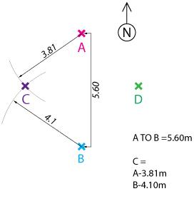
Take four tent pegs and stake them in the ground approx 5 to 10m apart in a cross section with pegs running north south and east west. Use your directional compass to orientate the pegs. The measurements between pegs are not crucial distance would be relative to the size of the area. Mark these on your plan and label them A,B,C and D.
-
To measure obstacles from within your area you can use a triangulation method to pin point location of obstacles. See file “Triangulation Method Explained.pdf” for more details.
-
Measure the distance from peg A to peg B and record this on the side of the page.
Now use the triangulation method to locate peg C. To do this measure the distance from peg A to Peg C and record on the side of the page. Then measure the distance from Peg (B) to Peg (C) and record on the side of the page.
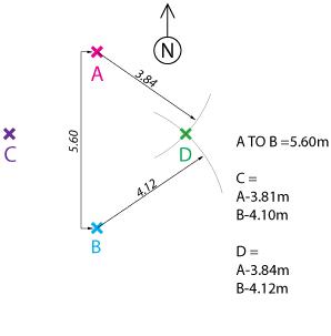
Repeat this process but this time we are looking for location of point “D” take measurements from A to D and B to D
- These four pegs will become datum points from which all other objects can be located using the triangulation method.
- Record the direction of North which should run in line with peg A and peg B
- Stand in the centre of the pegs and roughly sketch in the surrounding obstacles, buildings and services. Try to draw them as close to their location as possible.
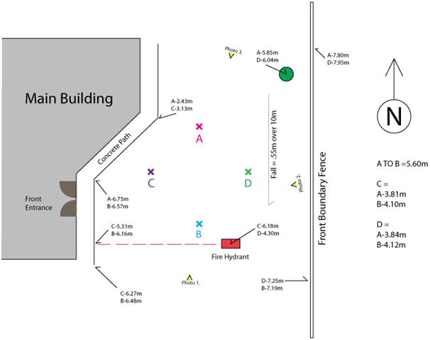
- Now we must locate the various obstacles in relation to our pegs. We need only choose two pegs to measure from. For the triangulation method to work accurately we should use the two pegs that are relatively a similar distance from the obstacle we are measuring. Take a measurement from the first peg, record the measurement beside the obstacle and record the peg we used to measure from. Repeat the process for the second peg. See example plan below.
- If your obstacle is a fence line you will need to take measurements for two locations to get the line of the fence.
- Now all of your obstacles should have two measurements beside them that we can use later when drawing an accurate scaled plan.
- Next take a measurement of the fall on the ground level if applicable. This can be done with a string line level or a laser level in either case you must record the amount of fall over a set distance. For example 550mm over 15m. Note that the distance measured should have a reasonably consistent fall. That is if the fall increases or decreases significantly you may need to take a few measurements to give an accurate description of the fall that exists on site.
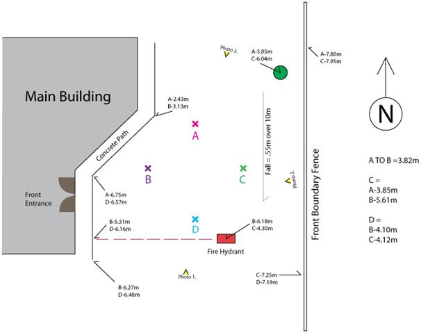
Along with any site plan, photos should be taken of all aspects of the site. As you are taking photos record the location and the direction of view for each photo. Record this information on your site plan and label your photos accordingly.
Look for any services underground ask the customer if they have locations for any services? Record any known service locations on the plan including the direction the service runs? Notice on the example plan the fire hydrant and the location of the underground pipe marked in red and located with a triangulation measurement at both ends.
Consider the logistics of the area such as pedestrian traffic flow, vehicle access for future use, overhead obstacles, supervision during play times and any other factors that may be worth considering when preparing a concept or quote. Take a good look around the site and try to get an understanding of the surroundings.
Before you leave double check you have not forgot to record any information as it is far easier to record it now than drive back at a later stage.
PREPARING A SCALED SITE PLAN
Now that we have been out to site and taken down all the information we will need to prepare an accurate scaled site plan. This will need to be done at home with on an open flat work space so as to record accurate information on the scaled site plan. You will require the following items:
- Grid paper with grid sizes 1cm x 1cm exactly
- Grey lead pencil
- Geometric Compass
- Ruler
Use the information on your preliminary plan to construct your scaled site plan.
Your preliminary plan should look like this (yours hand drawn).
- Firstly mark north on your plan.
- Now we need to record the positions of our four tent pegs. Mark peg A on the plan roughly where you think it should be located then using a compass scribe an arch at the distance recorded on the preliminary plan. In our examples case this is 5.60m as our plan is scaled at 1cm = 1m the distance on our plan is 5.60cm. On this scribe line mark the location of peg B should be placed in the direction it would exist on site. On our example plan this would be below directly north south. Running your (A) and (B) pegs north south is a good idea as it ensures your plan is facing exactly the correct direction.
- Now locate peg B and peg C using the triangulation method.
- Once all four pegs are located you can triangulate the position of all the obstacles on your plan.
- Now record any fall that may exist.
- Lastly record the position of any photos taken and the direction of view. The names of the photos should correspond with the actual photo name so it is understood by the office which photo is which.
Tip: Try to draw this plan at home for practise – does it look like our plan?
Would you like to download our colour range of our playground equipment?
You can also download our scaled site plan 1:100 to assist you when drawing a scale plan.
Have a look at this file which is a finished example of the site plan we have drawn above with the playground sketched scaled into the plan 1:100.
Here is an example of one of our playgrounds sized up so you can measure up and use our components to construct your very own playground.
Because our playgrounds are modular and made up for 1.2m x 1.2m intervals you can also download a scaled plan at 1:120 so you can draw your equipment using our modulr system for precise planning.
Return back to the home page of Imaginationplay, see our range of softplay indoor playground equipment or outdoor playground equipment and accessories. |